 |
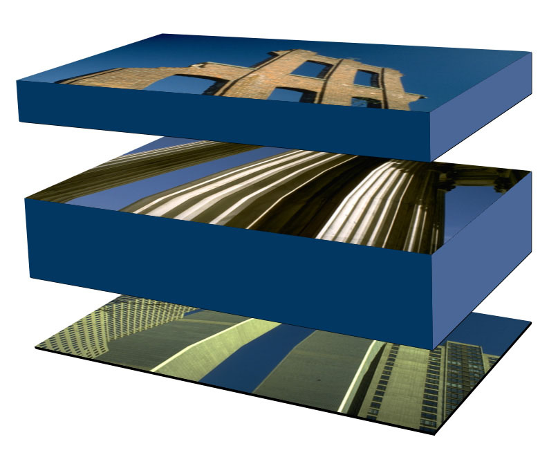
Viewer Height: Sets the height of the layers
Layer 2: Top layer
Layer 1: Middle layer
Background Layer: Bottom layer
Layer Thickness: The thickness of layers
Layer Separation: Spacing between layers
Overview
Super Blend is a compositing filter that allows you to superimpose up to five layers, then adjust and animate the view through each layer. If you imagine the composition as a series of layers of paint applied to a background layer, Super Blend lets you to move in and out of the composition by adjusting the distance between the viewer’s eye and the background, the thickness of the layers, and the distance separating each layer. This filter also offers a PixelChooser for greater creative control.
Parameter Controls
Presets and Common Controls
BCC filters come with a library of factory installed presets plus the ability to create your own custom presets and preview them with the BCC FX Browser™.
BCC filters also include common controls that configure global effect preferences and other host-specific effect settings.
For more information about working with presets and other common controls, Click Here.
Compare Mode
The BCC Compare Mode provides a convenient mechanism to compare the effect result with the original source layer. It provides several variations on basic split-screen views with the filtered clip placed next to the unedited original.
For more information on the Compare Mode, Click Here.
Compare Mode pop-up: Controls what is displayed by the Compare Mode. The options are:
- Off shows the output of the filter.
- Side By Side the left side of the output shows half of the incoming image, and the right side shows the same half of the image as processed by the filter. When in Side-by-Side mode, the corresponding Slide and Right Offset sliders become available.Wipe enables the user to interactively wipe the effect across the image. The left side of the wipe bar on the image output shows the unfiltered image, while the right side of the wipe bar shows the filtered result. When in Wipe mode, the corresponding Wipe slider becomes available.
- Wipe/Slide operates as a Wipe function when Wipe is selected in Compare Mode, and as a Slide function when Side-‐By-‐Side is selected in Compare Mode. When in Wipe mode, adjustments to this parameter moves the vertical wipe bar across the image; the region on the left of the wipe bar shows the original unfiltered image, while the region on the right shows the filtered result. When in Slide mode, adjustments to this parameter pans the image in the viewer window, maintaining the spatial relationship in the viewer between the before and after images.
- Right Offset provides a way to adjust the spatial relationship between the unfiltered original image and the filtered result in the viewer window. Adjustments to this parameter will offset the position of the filtered image in the viewer.
Viewer Height sets the distance between the viewer’s “eye” and the background layer in the composition. At the default value of 0, the viewer is placed just above the background layer and below all of the other layers in the composition. Thus only the background layer is visible. As Viewer Height increases, the viewer’s eye moves through each successive layer. At a value of 100, only the topmost layer is visible.
Selecting the Normalize Height checkbox scales the Viewer Height by the sum of the Layer Separation and Layer Thickness values for all the active layers so that the total height of the effect equals 100 units. If Normalize Height is deselected, then the Viewer Height is measured in the same absolute units as Layer Separation and Layer Thickness, and the total height of the effect may be taller or shorter than 100 units.
For example, when Normalize Height is selected, a Viewer Height of 100 always places the viewer immediately above the topmost layer. When Normalize Height is deselected, a Viewer Height value of 100 does not necessarily place the viewer above the last layer. Instead, the location of the viewer in relation to the layers depends on the number of layers, the distance between the individual layers, and the thickness of each layer.
The Background menu sets the background layer. Input uses the layer to which Super Blend is applied to as background. Transparent makes the background transparent.
Layer 1-5 Parameter Groups
Select the Layer 1 On checkbox to include the clip or layer in the effect. Leave this option deselected to exclude the layer from the effect.
The Layer 1 menu lets you select any clip or layer in your composition to use as Layer 1.
Separation Layer 1 sets the vertical distance between Layer 1 and the layer below. For example, if Separation Layer 1 is 10, when Viewer Height is 10 or less, the Background Layer is visible. When Viewer Height is greater than 10, Layer 1 is visible.
Opacity Layer 1 scales the opacity of the layer. At an Opacity Layer 1 value of 100, the layer is completely opaque. At a value of 0, Layer 1 is completely transparent.
Thickness Layer 1 determines the thickness of Layer 1. For example, if Thickness Layer 1 is 5 and Separation Layer 1 is 10, when Viewer Height is 10 or less the background is visible. When Viewer Height is between 10 and 15, the viewer is “inside” Layer 1. The opacity of the layer increases as the Viewer Height approaches 15. When Viewer Height is greater than 15, Layer 1 is fully visible and its opacity is determined solely by the Opacity Layer 1 setting.
The Apply Mode Layer 1 menu controls how Layer 1 is composited with the layers below. For descriptions of all the possible Apply Modes, Click Here.
Apply Mix Layer 1 controls the mix of the specified Apply Mode Layer 1 with the Normal apply mode. If the Apply Mode Layer 1 is Normal, Apply Mix Layer 1 has no effect. If Apply Mix Layer 1 is 0, Apply Mode Layer 1 has no effect. Increase Apply Mix Layer 1 to blend the Apply Mode Layer 1 setting with the Normal apply mode.
- Note: The Layer 2-5 Parameters function in the same manner as the corresponding Layer 1 parameters, but apply to the additional layers in the composition.
Height Maps Parameter Group
The Height Maps parameters allow you to apply up to three independent height maps to vary the viewer’s height from point to point in the image. You can choose a different source clip or layer for each height map. The filter uses the source map layer’s alpha, luma, or color channels to determine the viewer height for each pixel in the composite.
For example, this image shows the relative height of each source layer before height maps are applied.
 |
Layer 3: Top slide of image
Layer 2: Middle slide of image
Layer 1: Bottom slide of image
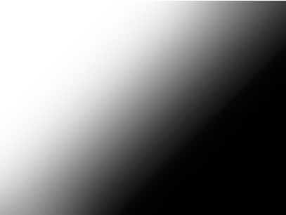
This gradient is applied as a Height Map Layer, and its luma channel used as the Map Channel.
 |
Higher luma channel values (white areas) in the Map Layer place the viewer’s eye higher in the composite. Lower luma values (black areas) place the viewer’s eye lower in the composite.
 |
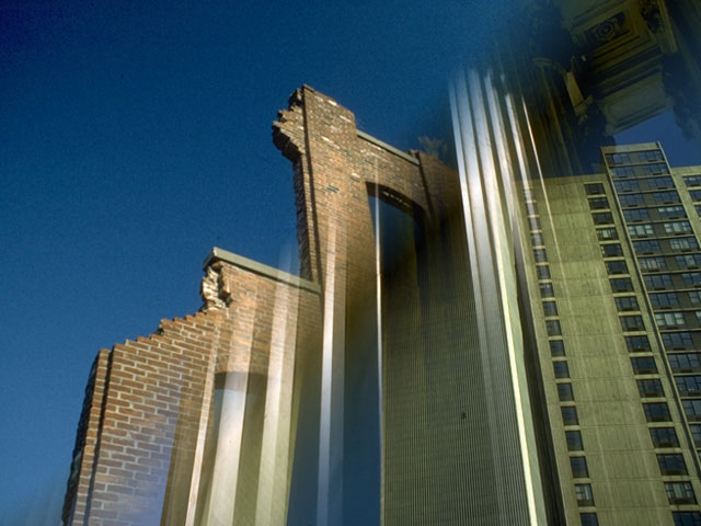
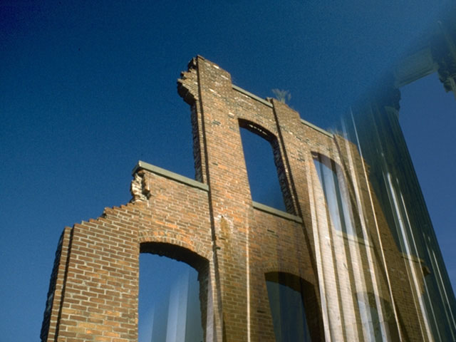
The Height Maps control only the relative viewer height across the image, meaning you can still move Viewer Height up and down to adjust how much of each layer is visible in the composite. For example, increasing Viewer Height displays more of the topmost image (Layer 3) and none of the bottom-most image (Layer 1).
 |
Select the Use Height Maps checkbox to turn the height maps on and enable the height map controls.
Select the Mask with Height Maps checkbox to mask the output of the filter with a composite of the alpha channels in all three height maps.
The Source menu sets which clip or layer in the composition is used to generate Map 1. If None is selected, the map is not used, and the other Map 1 parameters have no affect.
The Channel menu sets which channel in the Source 1 Map is used to create Map 1.
- Note: If Luma or one of the RGB color channels is chosen, the height offsets in the map are scaled by the alpha values in the Source 1 Map layer.
The height map is created by comparing each pixel’s Channel Map 1 value and the Reference menu value. The difference between the two values in each pixel scales the Viewer Height at that pixel.
- When Reference is Black, each pixel’s channel value is compared to a value of 0. In this case, the channel values directly scale the Viewer Height.
- When Reference is Gray, 128 is subtracted from each pixel’s channel value, and the Viewer Height is scaled by the result.
- When Reference is White, each pixel’s channel value is subtracted from 255, and the Viewer Height is scaled by the result.
Amount Map 1 determines the direction and amount of displacement applied equally to all height values in the map. Positive values increase the Viewer Height, while negative values decrease the Viewer Height.
- Note: The remaining controls in this section adjust Map 2 and Map 3. These parameters function identically to the corresponding Map 1 controls described above.
Mix with Original blends the source and filtered images. Use this parameter to animate the effect from the unfiltered to the filtered image without adjusting other settings, or to reduce the effect of the filter by mixing it with the source image.
PixelChooser
The BCC PixelChooser provides simple, built-in masking of the effect result. The PixelChooser is generally used to select a portion of the image and restrict an effect to just the selected area while maintaining the original image content in unselected regions. The selection can be based on geometric shapes or on the image’s luma/color properties.
For more information on the PixelChooser, Click Here.