 |
 |
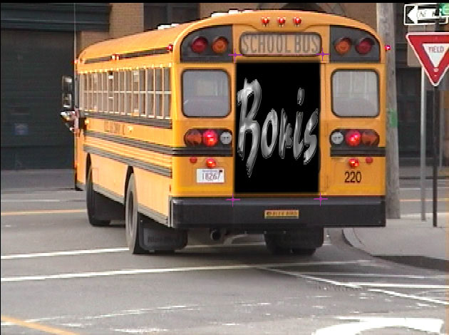 |
| Original image | Corner Pin Image | Filtered image |
Deprecated – replaced by BCC Corner Pin Studio
With the introduction of Continuum 2020 we recommend the use of BCC Corner Pin Studio, our next generation of corner pinning that simplifies the work of creating corner pin inserts. BCC Corner Pin Studio is powered by Mocha planar tracking and includes several post processing options for foreground color correction, edge chokes, drop shadow, light wrap and 21 unique compositing blend modes.
NOTE: BCC Corner Pin Studio is not available for FCPX and Motion users at this time. Final Cut and Motion users have access to the original BCC Corner Pin.
Overview
The BCC Corner Pin filter allows you to map media to a specific area on a moving object in a media file. For example, your media includes a moving bus with an advertisement on its side. You could use Corner Pin to track and replace the advertisement with a logo.
Function
Presets and Common Controls
BCC filters come with a library of factory installed presets plus the ability to create your own custom presets and preview them with the BCC FX Browser™.
BCC filters also include common controls that configure global effect preferences and other host-specific effect settings.
For more information about working with presets and other common controls, Click Here.
- Vegas Pro Workflow Tip: To use the Light Wrap feature in Vegas Pro you must apply the filter in Custom Composite Mode. For more information on working with Custom Composite Modes in Vegas, Click Here.
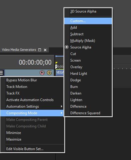
Using Custom Composites in Vegas Pro
The Corner Pin Source menu sets the track that you want to corner pin onto the filtered track. The choices are None, Filter Layer, 1st Below or 2nd Below. In general, the easiest method is to place the filtered track on a track above the corner pin image.
If the source image is opaque, selecting the Opaque Source checkbox can speed rendering and preview times. If your source is partially transparent, deselect this option for best results. You must deselect this checkbox to apply the filter to a matte.
Corner 1, Corner 2, Corner 3 and Corner 4 Parameter Groups:
The Corner 1, Corner 2, Corner 3 and Corner 4 position controls define the four corner pin trackers. However, in general it is easier to position the onscreen controls and use the sliders for finetuning by selecting the Track on the Fly checkbox. The onscreen controls are color coded: Corner 1 is red, Corner 2 is green, Corner 3 is yellow, and Corner 4 is blue.
Crop Parameter Group
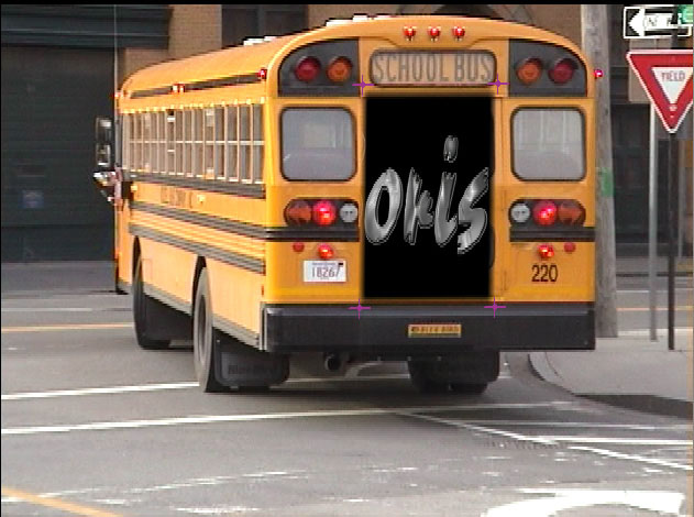
The Crop controls allow you to crop the edges of the media in the Corner Pin Source track. The Crop Left, Crop Top, Crop Right, and Crop Bottom settings determine the width, in pixels, of the cropped area on each edge of the image.
 |
 |
| Crop Left | Crop Left=29, Crop Right=18 |
Scale and Offset Parameter Group
Scale X and Scale Y scale the rendered image after tracker data is applied on the X and Y axis respectively. When the Lock Scale to X checkbox is selected, Scale X sets the scale amount in both directions.
Master Offset X and Master Offset Y allow you to change the Offset X or Offset Y parameters for each of the four corners with one control.
The numbered Corner Offset X and Corner Offset Y parameters, allow you to offset the applied image on the X and Y axis for each of the four corners. This is useful if you want to track one area, then apply the effect to a different area. For example, you want to add a new advertisement next to an existing ad on the side of a moving bus. You would track the current ad, then offset the four corners to pin the new ad to the right of the existing ad.
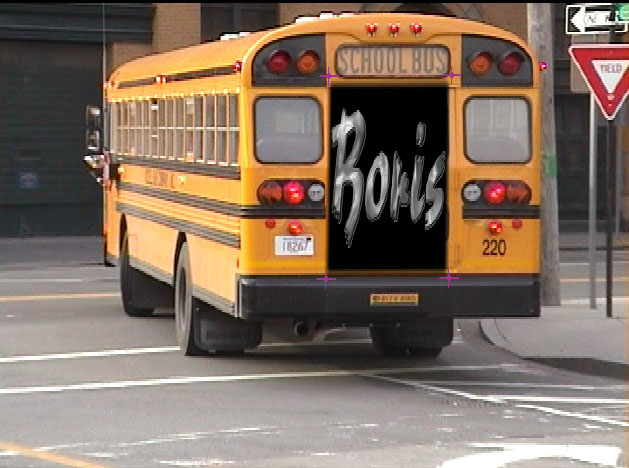
The Render menu is a display control that includes the following options.
- Pin Over Source displays the corner pin image composited over the filtered track.
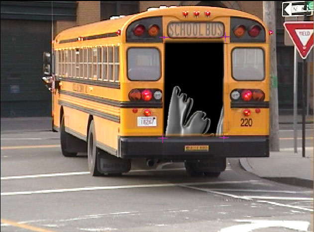
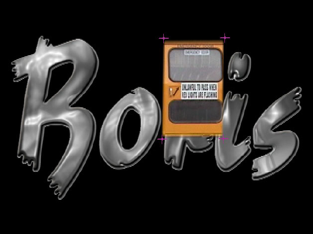
- Corner Pin Only displays the corner pin image composited over the full size corner pin image.
- Punch Hole displays the filtered track with an alpha channel where the corner pin image will appear. Tracks lower in the timeline are visible through the resulting “hole.”
- Show Corner Region displays the full size corner pin track inside the corner pin region with an alpha channel outside where the corner pin image will be placed. Tracks lower in the timeline are visible through the resulting alpha channel.
 |
 |
| Composite menu=Pin Over Source | Composite menu=Corner Pin Only |
 |
 |
| Composite menu=Punch Hole | Composite menu=Show Corner Region |
Edge Width controls the width of the edge that is generated by choking the alpha channel of the corner pin image. Higher numbers result in a larger border. If Edge Width is set to a value of 0, Edge Softness and Edge Smoothness have no affect.
Edge Softness softens the edge of the corner pin image. A value of 0 creates a hard edge; increasing this value increasingly softens the edge of the image. If Edge Softness is set to a value of 0, Edge Smoothness has no affect.
Edge Smoothness controls the gradation of the edge.
Light Wrap Parameter Group
The Light Wrap parameters reflects the background image around the edges of the corner pin image to form a border. This creates the illusion that light from the background is reflected onto the foreground. This creates a more convincing composite by making it appear as if the images were shot in the same environment.
Wrap Lightness sets the lightness value of the reflected image. Negative values make the reflection darker and positive values make the reflection lighter.
The Wrap Softness parameter softens the edges of the border that is reflected or wrapped.
Wrap Width controls the width of the reflection or wrap that is generated. Higher numbers result in a larger border.
The Wrap Apply Mode menu determines the method that is used to composite the border. For descriptions of all the possible Apply Modes, Click Here.
Composite Parameter Group
Opacity scales the opacity of the corner pin image. At an Opacity value of 100, the image is completely opaque. At a value of 0, the image is completely transparent.
The Apply Mode menu controls how the source and corner pin images are composited. This filter is most useful with Apply Modes other than Normal. For descriptions of all the Apply Modes, Click Here.
Apply Mix blends the Apply Mode setting with the Normal apply mode. The resulting mixed mode is used to composite the Corner Pin media over the filtered layer. For example, if Apply Mode is set to Lighten, then an Apply Mix value of 0 uses the Normal apply mode; an Apply Mix value of 100 uses the Lighten apply mode. An Apply Mix value of 50 blends the two apply modes equally.
- Note: You can use Apply Mix to soften the affect of a given apply mode.
Deselecting the Use Motion Trackers checkbox allows you to override the corner pin trackers and use the onscreen controls to manually place your corner pin image.
Mocha Motion Tracker (Workflow in Continuum 2019 and newer)
The Continuum Mocha Motion Tracker allows you to track the motion of an object, then use the motion path to drive other geometric properties of the effect without the need for keyframing. For more information on general usage of the Mocha Motion Tracker, Click Here. Note that Corner Pin tracking has some unique workflow consideration which are further discussed here. The Corner Pin effect is ultimately driven by the locations of the four pin points, and when you first open the Mocha Motion Tracker UI you will be presented with four independent tracking points. While it would be possible to track the four corner points as completely independent tracks, that is not the optimum way to approach corner pin tracking with Mocha, where the underlying planar tracking engine can provide a more robust track by analyzing the motion of a single plane than by analyzing the four corners separately. The recommended workflow for Corner Pin tracking in Continuum 2019 and up is as follows:
- Launch the Mocha Motion Tracker UI from the Corner Pin effect
- Ignore (or even disable the process icon) the four independent point layers. If they are not disabled you may want to move them onto some feature that is easy to track just to avoid any distractions due to lost tracks when to tracking the real target plane (which will be done in the next step.)
- Create a brand new fifth track layer by using conventional mocha tracking tools to track the overall plane you want to replace. Don’t worry yet about the exact corner locations – focus instead on getting a solid track of the plane itself, being sure to adjust the tracking mode in the mocha UI to +skew or +Perspective if your plane moves with any skew or perspective during the course of the shot.
- Select each of the 4 point track layers and in the layer pane and one-by-one link them to the main layer track (created in the previous step).
- Select each of the 4 point track layers and move their cross-hairs one-by-one to the exact corner location for the pin on that particular frame.
- Save and apply back to the host and scrub the timeline. If the main plane track is solid you should then see all four corners points following the intended pin location exactly.
Legacy Motion Tracker Parameter Group (Continuum 11 and earlier)
The Motion Tracker parameter groups allows you to track the motion of an object, then use the motion path data to control another aspect of the effect. For example, track a detergent bottle and pin a new label to the bottle. Because the Corner Pin Tracker includes four trackers, it includes the following additional parameters. Because the Corner Pin Tracker includes four trackers, the following parameters appear in the Tracker 1, Tracker 2, Tracker 3 and Tracker 4 parameter groups. In other filters, these parameters appear in the Motion Tracker parameter group. The parameters are Start Tracking Frame, End Tracking Frame, Target Width, Search Width and Tracker Auto-Man.
The Track menu determines which corner pin trackers are analyzed when you select the Track on the Fly checkbox and click Play. The options are All, Corner 1, Corner 2, Corner 3 and Corner 4. Data is created for all currently selected trackers.
Selecting a Lock Tracker checkbox locks the specified Tracker. Tracking data is not generated for a locked Tracker, even if you track again. For example, set the Track menu to All, select the Track on the Fly checkbox and click Play. Trackers 1, 2 and 3 track correctly, but Tracker 4 has some issues. You could lock Trackers 1, 2 and 3, adjust Tracker 4 then track again. Even if you click the Reset Tracker checkbox, locked Trackers are not affected.
When the Use Start -End 1 for All checkbox is selected, the Start Tracking Frame and End Tracking Frame parameter values set in Tracker 1 apply to all trackers. Deselect this checkbox to set separate values for individual trackers.
When the Use Width 1 for All checkbox is selected, the Target Width and Search Width parameter values set in Tracker 1 apply to all trackers. Deselect this checkbox to set separate values for each tracker.
Overview of Using the Corner Pin Tracker:
The steps below provide an overview of the Corner Pin Tracker process. The sections that follow provide detailed information on each step.
1. Apply the Corner Pin Tracker filter directly to a clip in the timeline containing the moving area that you want to replace.
2. Choose the track that you want to replace the moving area from the Corner Pin Source menu. The easiest method is to place the filtered track on a track above the corner pin image.
3. If necessary, select the View Preprocessed Source checkbox and adjust the Motion Tracker Preprocess parameters to make your source image easier to track. For example, you could increase the contrast for better results. Make sure to deselect the View Preprocessed Source checkbox before you select the Track On-the-Fly checkbox and begin tracking.
4. Select the Track On-the-Fly checkbox and use the onscreen controls to position a motion tracker on each of the four corners of the region to replace.
5. Generate the tracker data using the parameters in the Motion Tracker parameter group. With the Track On-the-Fly checkbox still selected, press Play. The filter calculates the tracking data. When you select this checkbox, the chosen effect does not display. Once you finish tracking, deselect this checkbox to view the applied effect.
Final Cut Pro users need to choose Mark > Play > Every Frame. Premiere Pro users need to step through single frames.
The media in the Corner Pin Source track is automatically positioned in the region defined by the four corner trackers. The media distorts as necessary to fit the region as it moves and changes shape.
Correcting Corner Pin Legacy Tracking Errors (Continuum 11 and earlier)
If the Corner Pin Tracker cannot locate the Target region during analysis, errors can occur. You can use one of the following methods to finetune your results. Before finetuning, you should select the Lock Tracker checkbox for any Tracker that generated accurate data.
- Adjust the parameters in the Preprocess parameter group and track again.
- If this still doesn’t correct the error, you can manually correct the tracker position by keyframing the Tracker Center KF. See “Correcting Motion Tracker Errors”.
- Alternatively, you can manually position the Corner Pin image in problem areas by using the Tracker Auto-Man parameter.